ThePCEnthusiast is supported by its readers. When you purchase products via our links, we may earn an affiliate commission. See our site disclosure here.
Gigabyte X99 Champion Series Motherboards Unleashed
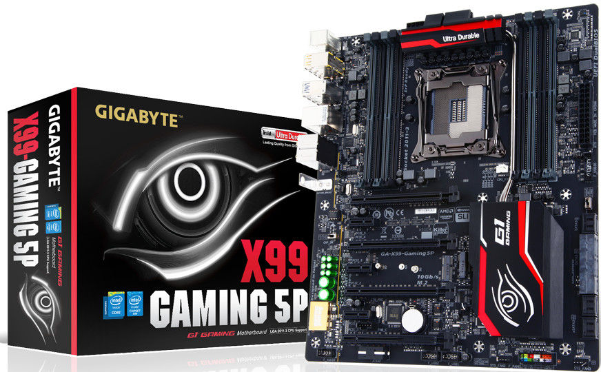
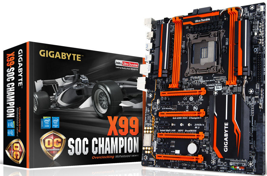
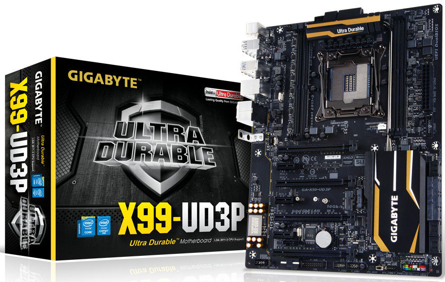
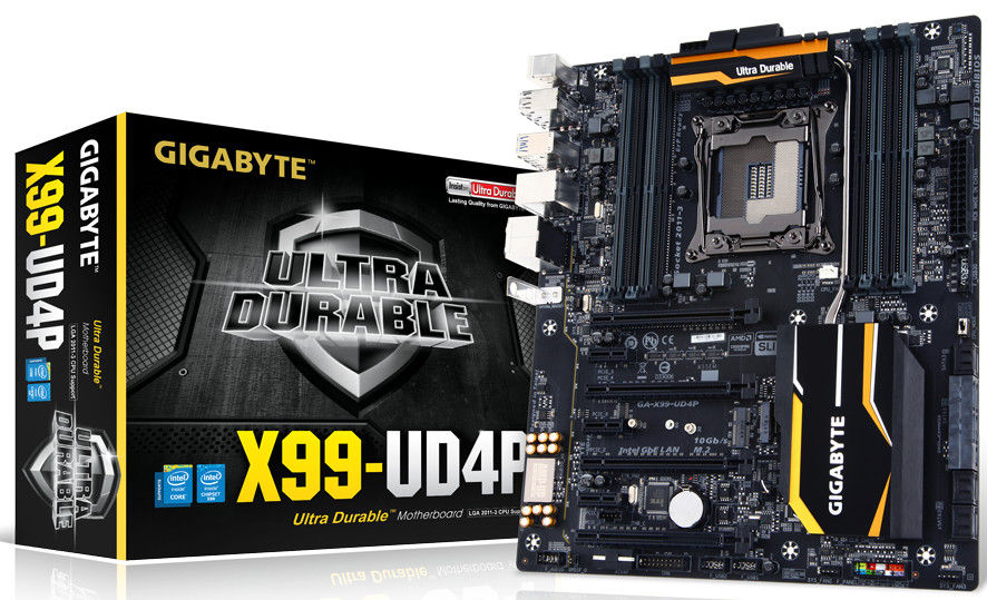
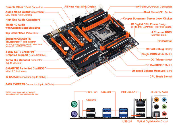
Gigabyte has recently announced four high performance motherboard under their X99 Champion Series – the Gigabyte X99-SOC Champion, Gigabyte X99-Gaming 5P, Gigabyte X99-UD4P and Gigabyte X99-UD3P. These X99 Champion motherboards supports the latest Intel Core i7 Processor Extreme Editions and DDR4 up to 3200MHz speed with Intel XMP. They also feature Genuine All Digital Power Design with IR Digital PWM and IR PowIRstage ICs, and 4-way graphics with premium PCEIe lane. Check out the rest of their features from the official release below.
Gigabyte X99 Champion Series Features
DDR4 memory modules are available at a stock frequency of 2133 MHz, but memory vendors encode XMP profiles which can automatically modify the frequency and timings of the supported memory modules to work in par with your CPU. With the X99 Champion Series, GIGABYTE is offering a tested and proven platform that ensures proper compatibility with profiles up to 3200 MHz, and exclusively 3400 MHz for the X99-SOC Champion.
Paired with DDR4 memory such as the Corsair Limited Edition Orange Dominator Platinum kit, which was custom designed for the GIGABYTE X99-SOC Champion motherboard, users can take advantage of better responsiveness during gaming and faster operation execution in memory demanding works applications.
Corsair Dominator Platinum Series 16GB DDR4 – DRAM 3400MHz C16 Memory Kit
GIGABYTE X99 Champion series motherboards also provide support for RDIMM memory which allows users to use greater density memory sticks up to 16GB per stick. This paired with a range of exciting features such as the GIGABYTE’s Amp-Up Audio, Killer E2200 or Intel gigabit Ethernet controller and unique GIGABYTE Ultra Durable features means that users can truly build a PC that brings them exceptional performance and durability.
Genuine All Digital Power Design
GIGABYTE X99 Champion series motherboards use an all-digital CPU power design from International Rectifier which includes both digital 4th Generation digital PWM Controller and industry-leading 3rd Generation PowIRstage controllers. These 100% digital controllers offer incredible precision in delivering power to the motherboard’s most power-hungry and energy-sensitive components, allowing enthusiasts to get the absolute maximum performance from their next generation Intel Core processors.
IR Digital PWM and IR PowIRstage ICs
This new generation of IR digital power controllers and PowIRstage ICs feature Isense technology, which provides more precise current sensing accuracy. This helps evenly distribute the thermal loading between the PowerIRstage ICs, preventing the overheating of each individual PowIRstage, resulting in longer lifespan and better reliability.
Server Level Chokes
GIGABYTE X99 Champion series motherboards features Server Level Chokes.
Server level reliability
High current capacity
New design reduces heat created by power loss and provides efficient power delivery to CPU VRM area.
Long Lifespan Durable Black Solid Caps
GIGABYTE X99 Champion series motherboards integrate the absolute best quality solid state capacitors that are rated to perform at the maximum efficiency for extended periods, even in extreme performance configurations. This provides peace of mind for end users who want to push their system hard, yet demand absolute stability.
6x (30μ) Gold Plating
GIGABYTE X99 Champion series motherboards come equipped with a 30 micron thick gold plating, 4 PCIe slots and over the DIMM slots, which means that enthusiasts can enjoy better connectivity, absolute reliability and longevity for the diverse connectors overtime, without having any concerns about corroded pins and bad contacts.
Creative Sound Core3D Quad-Core Audio Processor Plus Creative SBX Pro Studio Audio Suite
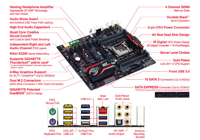
Exclusive to the gaming motherboard of the X99 Champion series, the X99-Gaming 5P features the world’s first Quad-Core Creative Sound Core3D Audio Processor plus Advanced Creative SBX PRO STUDIO Audio Suite. SBX Pro Studio suite of audio playback technologies delivers a new level of audio immersion. Realistic surround sound, the ability to clearly hear specific sounds in a gaming environment are just a few elements of SBX Pro Studio that enhances the overall experience, be it movies, games or music.
Realtek ALC 1150 115dB SNR HD Audio with Built-In Reat Audio Amplifier
Featured across the other Champion motherboards is the Realtek ALC1150, a high-performance multi-channel High Definition Audio Codec that delivers an exceptional audio listening experience with up to 115dB SNR, ensuring users get the best possible audio quality from their PC.
The ALC1150 provides ten DAC channels that simultaneously support 7.1-channel sound playback, plus 2 channels of independent stereo sound output (multiple streaming) through the front panel stereo outputs. Two stereo ADCs are integrated and can support a microphone array with Acoustic Echo Cancellation (AEC), Beam Forming (BF), and Noise Suppression (NS) technologies. The ALC1150 incorporates Realtek proprietary converter technology to achieve Front differential output 115dB Signal-to-Noise ratio (SNR) playback (DAC) quality and 104dB SNR recording (ADC) quality.
Killer Networking
The GIGABYTE X99-Gaming 5P motherboard features the Killer E2200, a high-performance, adaptive gigabit Ethernet controller that offers better online gaming and online media performance compared to standard solutions. The Killer E2200 features Advanced Stream Detect technology, which identifies and prioritizes all network traffic to ensure important applications that require high-speed connectivity are prioritized over less important traffic.
Intel GbE LAN with cFos Internet Accelerator Software
Additional GIGABYTE X99 Champion series motherboards feature cFos Speed, a network traffic management application which helps to improve network latency, maintaining low ping times to deliver better responsiveness in a crowded LAN environment. cFos Speed works in a similar way to an OS driver, monitoring network traffic packets at the application layer, allowing optimization and improved network performance for specific applications.
Support for Intel® Core™ i7 processors in the LGA2011-3 package
L3 cache varies with CPU
(Please refer “CPU Support List” for more information.)
Chipset
Intel® X99 Express Chipset
Memory
4 x DDR4 DIMM sockets supporting up to 32 GB of system memory
* Due to a Windows 32-bit operating system limitation, when more than 4 GB of physical memory is installed, the actual memory size displayed will be less than the size of the physical memory installed.
4 channel memory architecture
Support for DDR4 3333(O.C.) / 3200(O.C.) / 3000(O.C.) / 2800(O.C.) / 2666(O.C.) / 2400(O.C.) / 2133 MHz memory modules
Support for non-ECC memory modules
Support for Extreme Memory Profile (XMP) memory modules
Support for RDIMM 1Rx8 memory modules (operates in non-ECC mode)
(Please refer “Memory Support List” for more information.)
Audio
Realtek® ALC1150 codec
High Definition Audio
2/4/5.1/7.1-channel
Support for S/PDIF Out
LAN
Intel® GbE LAN chip (10/100/1000 Mbit)
Expansion Slots
2 x PCI Express x16 slots, running at x16 (PCIE_1,PCIE_2)
* For optimum performance, if only one PCI Express graphics card is to be installed, be sure to install it in the PCIE_1 slot; if you are installing two PCI Express graphics cards, it is recommended that you install them in the PCIE_1 and PCIE_2 slots.
2 x PCI Express x16 slots, running at x8 (PCIE_3,PCIE_4)
* The PCIE_4 slot shares bandwidth with the PCIE_1 slot. When the PCIE_4 slot is populated, the PCIE_1 slot will operate at up to x8 mode.
* When an i7-5820K CPU is installed, the PCIE_2 slot operates at up to x8 mode and the PCIE_3 operates at up to x4 mode.
(All PCI Express x16 slots conform to PCI Express 3.0 standard.)
3 x PCI Express x1 slots
(All PCI Express x1 slots conform to PCI Express 2.0 standard.)
Multi-Graphics Technology
Support for 4-Way/3-Way/2-Way AMD CrossFire™/NVIDIA® SLI™ technology
* The 4-Way NVIDIA® SLI™ configuration is not supported when an i7-5820K CPU is installed. To set up a 3-Way SLI configuration, refer to “1-6 Setting up AMD CrossFire™/NVIDIA® SLI™ Configuration.”
Storage Interface
Chipset:
1 x M.2 PCIe connector
(Socket 3, M key, type 2242/2260/2280 PCIe x4x2/x1 SSD support)
* Support for M.2 PCIe SSDs only.
1 x SATA Express connector
6 x SATA 6Gb/s connectors (SATA3 0~5)
Support for RAID 0, RAID 1, RAID 5, and RAID 10
* Only AHCI mode is supported when an M.2 PCIe SSD or a SATA Express device is installed.
(M2_20G and SATA Express connectors can only be used one at a time. The SATA Express connector becomes unavailable when an M.2 SSD is installed, but the SATA3 4/5 connectors are still functional.)
4 x SATA 6Gb/s connectors (sSATA3 0~3), supporting IDE and AHCI modes only
(An operating system installed on the SATA3 0~5 ports cannot be used on the sSATA 0~3 ports.)
USB
Chipset:
2 x USB 3.0/2.0 ports available through the internal USB header
8 x USB 2.0/1.1 ports (4 ports on the back panel, 4 ports available through the internal USB headers)
Chipset + Renesas® uPD720210 USB 3.0 Hub:
4 x USB 3.0/2.0 ports on the back panel
Internal I/O Connectors
1 x 24-pin ATX main power connector
1 x 8-pin ATX 12V power connector
1 x 4-pin ATX 12V power connector
1 x OC PEG Power Connector
1 x SATA Express connector
10 x SATA 6Gb/s connectors
1 x M.2 Socket 3 connector
1 x CPU fan header
1 x water cooling fan header (CPU_OPT)
3 x system fan headers
1 x Thunderbolt™ add-in card connector
1 x OC Panel connector (for future expansion)
1 x front panel header
1 x front panel audio header
1 x S/PDIF Out header
1 x USB 3.0/2.0 header
2 x USB 2.0/1.1 headers
1 x serial port header
1 x Clear CMOS jumper
1 x power button
1 x reset button
1 x Clear CMOS button
1 x CPU mode switch
1 x OC Trigger switch
1 x DualBIOS switch
1 x BIOS switch
Voltage Measurement Points
Back Panel Connectors
1 x PS/2 keyboard port
1 x PS/2 mouse port
4 x USB 2.0/1.1 ports
4 x USB 3.0/2.0 ports
1 x RJ-45 port
1 x optical S/PDIF Out connector
5 x audio jacks (Center/Subwoofer Speaker Out, Rear Speaker Out, Line In, Line Out, Mic In)
I/O Controller
iTE I/O Controller Chip
H/W Monitoring
System voltage detection
CPU/System/Chipset temperature detection
CPU/CPU OPT/System fan speed detection
CPU/System/Chipset overheating warning
CPU/CPU OPT/System fan fail warning
CPU/CPU OPT/System fan speed control
* Whether the fan speed control function is supported will depend on the cooler you install.
BIOS
2 x 128 Mbit flash
Use of licensed AMI UEFI BIOS
Support for DualBIOS™
PnP 1.0a, DMI 2.7, WfM 2.0, SM BIOS 2.7, ACPI 5.0
Unique Features
Support for APP Center
* Available applications in APP Center may differ by motherboard model. Supported functions of each application may also differ depending on motherboard specifications.
@BIOS
Ambient LED
EasyTune
EZ Setup
Fast Boot
Cloud Station
ON/OFF Charge
Smart TimeLock
Smart Recovery 2
System Information Viewer
USB Blocker
V-Tuner
Support for Q-Flash
Support for Smart Switch
Support for Xpress Install
Bundle Software
Norton® Internet Security (OEM version)
Intel® Smart Response Technology
cFosSpeed
Operating System
Support for Windows 8.1/8/7
Form Factor
E-ATX Form Factor; 30.5cm x 26.4cm
Remark
Due to different Linux support condition provided by chipset vendors, please download Linux driver from chipset vendors’ website or 3rd party website.
Most hardware/software vendors may no longer offer drivers to support Win9X/ME/2000/XP. If drivers are available from the vendors, we will update them on the GIGABYTE website.
[/tab]
[tab]
CPU
Support for Intel® Core™ i7 processors in the LGA2011-3 package
L3 cache varies with CPU
(Please refer “CPU Support List” for more information.)
Chipset
Intel® X99 Express Chipset
Memory
8 x DDR4 DIMM sockets supporting up to 64 GB of system memory
* Due to a Windows 32-bit operating system limitation, when more than 4 GB of physical memory is installed, the actual memory size displayed will be less than the size of the physical memory installed.
Support for Extreme Memory Profile (XMP) memory modules
Support for RDIMM 1Rx8/2Rx8/1Rx4/2Rx4 memory modules (operates in non-ECC mode)
(Please refer “Memory Support List” for more information.)
Audio
Creative® Sound Core 3D chip
Support for Sound Blaster Recon3Di
TI Burr Brown® OPA2134 operational amplifier
High Definition Audio
2/5.1-channel
Support for S/PDIF Out
LAN
Qualcomm® Atheros Killer E2201 LAN chip (10/100/1000 Mbit)
Expansion Slots
2 x PCI Express x16 slots, running at x16 (PCIE_1/PCIE_2)
* For optimum performance, if only one PCI Express graphics card is to be installed, be sure to install it in the PCIE_1 slot; if you are installing two PCI Express graphics cards, it is recommended that you install them in the PCIE_1 and PCIE_2 slots.
2 x PCI Express x16 slots, running at x8 (PCIE_3/PCIE_4)
* The PCIE_4 slot shares bandwidth with the PCIE_1 slot. When the PCIE_4 slot is populated, the PCIE_1 slot will operate at up to x8 mode.
* When an i7-5820K CPU is installed, the PCIE_2 slot operates at up to x8 mode and the PCIE_3 operates at up to x4 mode.
(All PCI Express x16 slots conform to PCI Express 3.0 standard.)
3 x PCI Express x1 slots
(The PCI Express x1 slots conform to PCI Express 2.0 standard.)
1 x M.2 Socket 1 connector for the wireless communication module (M2_WIFI)
Multi-Graphics Technology
Support for 4-Way/3-Way/2-Way AMD CrossFire™/NVIDIA® SLI™ technology
* The 4-Way NVIDIA® SLI™ configuration is not supported when an i7-5820K CPU is installed. To set up a 3-Way SLI configuration, refer to “1-6 Setting up AMD CrossFire™/NVIDIA® SLI™ Configuration.”
Storage Interface
Chipset:
1 x M.2 PCIe connector
(Socket 3, M key, type 2242/2260/2280 SATA & PCIe x2/x1 SSD support)
1 x SATA Express connector
6 x SATA 6Gb/s connectors (SATA3 0~5)
Support for RAID 0, RAID 1, RAID 5, and RAID 10
* Only AHCI mode is supported when an M.2 PCIe SSD or a SATA Express device is installed.
(M2_10G, SATA Express, and SATA3 4/5 connectors can only be used one at a time. The SATA3 4/5 connectors will become unavailable when an M.2 SSD is installed in the M2_10G connector.)
Chipset:
4 x SATA 6Gb/s connectors (sSATA3 0~3), supporting IDE and AHCI modes only
(An operating system installed on the SATA3 0~5 connectors cannot be used on the sSATA3 0~3 connectors.)
USB
Chipset:
4 x USB 3.0/2.0 ports (2 ports on the back panel, 2 ports available through the internal USB header)
8 x USB 2.0/1.1 ports (4 ports on the back panel, 4 ports available through the internal USB headers)
Chipset + Renesas® uPD720210 USB 3.0 Hub:
4 x USB 3.0/2.0 ports on the back panel
Internal I/O Connectors
1 x 24-pin ATX main power connector
1 x 8-pin ATX 12V power connector
1 x PCIe power connector
1 x I/O shield audio LED power connector
1 x heatsink LED power connector
1 x M.2 Socket 3 connector
1 x SATA Express connector
10 x SATA 6Gb/s connectors
1 x CPU fan header
1 x water cooling fan header (CPU_OPT)
3 x system fan headers
1 x front panel header
1 x front panel audio header
1 x USB 3.0/2.0 header
2 x USB 2.0/1.1 headers
1 x Thunderbolt add-in card connector
1 x Clear CMOS jumper
1 x CPU mode switch
1 x audio gain control switch
Back Panel Connectors
1 x PS/2 keyboard port
1 x PS/2 mouse port
6 x USB 3.0/2.0 ports
4 x USB 2.0/1.1 ports
1 x optical S/PDIF Out connector
1 x RJ-45 port
5 x audio jacks (Center/Subwoofer Speaker Out, Rear Speaker Out, Line In/Mic In, Line Out, Headphone)
2 x Wi-Fi antenna connector holes
I/O Controller
iTE® I/O Controller Chip
H/W Monitoring
System voltage detection
CPU/System/Chipset temperature detection
CPU/CPU OPT/System fan speed detection
CPU/System/Chipset overheating warning
CPU/CPU OPT/System fan fail warning
CPU/CPU OPT/System fan speed control
* Whether the fan speed control function is supported will depend on the cooler you install.
BIOS
2 x 128 Mbit flash
Use of licensed AMI UEFI BIOS
Support for DualBIOS™
Support for Q-Flash Plus
PnP 1.0a, DMI 2.7, WfM 2.0, SM BIOS 2.7, ACPI 5.0
Unique Features
Support for APP Center
* Available applications in APP Center may differ by motherboard model. Supported functions of each application may also differ depending on motherboard specifications.
@BIOS
Ambient LED
EasyTune
EZ Setup
Fast Boot
Game Controller
Cloud Station
ON/OFF Charge
Smart TimeLock
Smart Recovery 2
System Information Viewer
USB Blocker
V-Tuner
Support for Q-Flash
Support for Smart Switch
Support for Xpress Install
Bundle Software
Norton® Internet Security (OEM version)
Intel® Smart Response Technology
Operating System
Support for Windows 8.1/8/7
Form Factor
E-ATX Form Factor; 30.5cm x 26.4cm
Remark
Due to different Linux support condition provided by chipset vendors, please download Linux driver from chipset vendors’ website or 3rd party website.
Most hardware/software vendors may no longer offer drivers to support Win9X/ME/2000/XP. If drivers are available from the vendors, we will update them on the GIGABYTE website.
[/tab]
[tab]
CPU
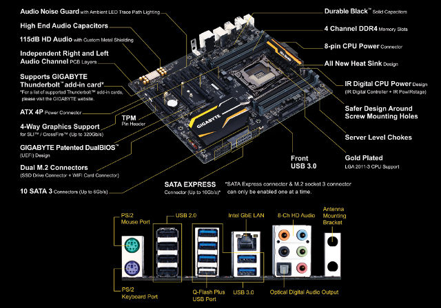
Support for Intel® Core™ i7 processors in the LGA2011-3 package
L3 cache varies with CPU
(Please refer “CPU Support List” for more information.)
Chipset
Intel® X99 Express Chipset
Memory
8 x DDR4 DIMM sockets supporting up to 64 GB of system memory
* Due to a Windows 32-bit operating system limitation, when more than 4 GB of physical memory is installed, the actual memory size displayed will be less than the size of the physical memory installed.
4 channel memory architecture
Support for DDR4 2800(O.C.) / 2666(O.C.) / 2400(O.C.) / 2133 MHz memory modules
Support for non-ECC memory modules
Support for Extreme Memory Profile (XMP) memory modules
Support for RDIMM 1Rx8/2Rx8/1Rx4/2Rx4 memory modules (operate in non-ECC mode)
(Please refer “Memory Support List” for more information.)
Audio
Realtek® ALC1150 codec
High Definition Audio
2/4/5.1/7.1-channel
Support for S/PDIF Out
LAN
Intel® GbE LAN chips (10/100/1000 Mbit)
Expansion Slots
2 x PCI Express x16 slots, running at x16 (PCIE_1, PCIE_2)
* For optimum performance, if only one PCI Express graphics card is to be installed, be sure to install it in the PCIE_1 slot; if you are installing two PCI Express graphics cards, it is recommended that you install them in the PCIE_1 and PCIE_2 slots.
2 x PCI Express x16 slots, running at x8 (PCIE_3, PCIE_4)
* The PCIE_4 slot shares bandwidth with the PCIE_1 slot. When the PCIE_4 slot is populated, the PCIE_1 slot will operate at up to x8 mode.
* When an i7-5820K CPU is installed, the PCIE_2 slot operates at up to x8 mode and the PCIE_3 operates at up to x4 mode.
(All PCI Express x16 slots conform to PCI Express 3.0 standard.)
3 x PCI Express x1 slots
(The PCI Express x1 slots conform to PCI Express 2.0 standard.)
1 x M.2 Socket 1 connector for the wireless communication module (M2_WIFI)
Multi-Graphics Technology
Support for 4-Way/3-Way/2-Way AMD CrossFire™/NVIDIA® SLI™ technology
* The 4-Way NVIDIA® SLI™ configuration is not supported when an i7-5820K CPU is installed. To set up a 3-Way SLI configuration, refer to “1-6 Setting up AMD CrossFire™/NVIDIA® SLI™ Configuration.”
Storage Interface
Chipset:
1 x M.2 PCIe connector
(Socket 3, M key, type 2242/2260/2280 SATA & PCIe x2/x1 SSD support)
1 x SATA Express connector
6 x SATA 6Gb/s connectors (SATA3 0~5)
Support for RAID 0, RAID 1, RAID 5, and RAID 10
* Only AHCI mode is supported when an M.2 PCIe SSD or a SATA Express device is installed.
(M2_10G, SATA Express, and SATA3 4/5 connectors can only be used one at a time. The SATA3 4/5 connectors will become unavailable when an M.2 SSD is installed in the M2_10G connector.)
Chipset:
4 x SATA 6Gb/s connectors (sSATA3 0~3), supporting IDE and AHCI modes only
(An operating system installed on the SATA3 0~5 connectors cannot be used on the sSATA3 0~3 connectors.)
USB
Chipset:
4 x USB 3.0/2.0 ports (2 ports on the back panel, 2 ports available through the internal USB header)
8 x USB 2.0/1.1 ports (4 ports on the back panel, 4 ports available through the internal USB headers)
Chipset + Renesas® uPD720210 USB 3.0 Hub:
4 x USB 3.0/2.0 ports on the back panel
Internal I/O Connectors
1 x 24-pin ATX main power connector
1 x 8-pin ATX 12V power connector
1 x PCIe power connector
1 x I/O shield audio LED power connector
1 x heatsink LED power connector
1 x M.2 Socket 3 connector
1 x SATA Express connector
10 x SATA 6Gb/s connectors
1 x CPU fan header
1 x water cooling fan header (CPU_OPT)
3 x system fan headers
1 x front panel header
1 x front panel audio header
1 x USB 3.0/2.0 header
2 x USB 2.0/1.1 headers
1 x Trusted Platform Module (TPM) header
1 x Thunderbolt™ add-in card connector
1 x Clear CMOS jumper
1 x CPU mode switch
Back Panel Connectors
1 x PS/2 keyboard port
1 x PS/2 mouse port
6 x USB 3.0/2.0 ports
4 x USB 2.0/1.1 ports
1 x RJ-45 port
1 x optical S/PDIF Out connector
5 x audio jacks (Center/Subwoofer Speaker Out, Rear Speaker Out, Line In, Line Out, Mic In)
2 x Wi-Fi antenna connector holes
I/O Controller
iTE® I/O Controller Chip
H/W Monitoring
System voltage detection
CPU/System/Chipset temperature detection
CPU/CPU OPT/System fan speed detection
CPU/System/Chipset overheating warning
CPU/CPU OPT/System fan fail warning
CPU/CPU OPT/System fan speed control
* Whether the fan speed control function is supported will depend on the cooler you install.
BIOS
2 x 128 Mbit flash
Use of licensed AMI UEFI BIOS
Support for DualBIOS™
Support for Q-Flash Plus
PnP 1.0a, DMI 2.7, WfM 2.0, SM BIOS 2.7, ACPI 5.0
Unique Features
Support for APP Center
* Available applications in APP Center may differ by motherboard model. Supported functions of each application may also differ depending on motherboard specifications.
@BIOS
Ambient LED
EasyTune
EZ Setup
Fast Boot
Cloud Station
ON/OFF Charge
Smart TimeLock
Smart Recovery 2
System Information Viewer
USB Blocker
V-Tuner
Support for Q-Flash
Support for Smart Switch
Support for Xpress Install
Bundle Software
Norton® Internet Security (OEM version)
Intel® Smart Response Technology
cFosSpeed
Operating System
Support for Windows 8.1/8/7
Form Factor
E-ATX Form Factor; 30.5cm x 26.4cm
Remark
Due to different Linux support condition provided by chipset vendors, please download Linux driver from chipset vendors’ website or 3rd party website.
Most hardware/software vendors may no longer offer drivers to support Win9X/ME/2000/XP. If drivers are available from the vendors, we will update them on the GIGABYTE website.
[/tab]
[tab]
CPU
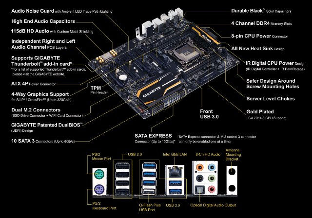
Support for Intel® Core™ i7 processors in the LGA2011-3 package
L3 cache varies with CPU
(Please refer “CPU Support List” for more information.)
Chipset
Intel® X99 Express Chipset
Memory
4 x DDR4 DIMM sockets supporting up to 32 GB of system memory
* Due to a Windows 32-bit operating system limitation, when more than 4 GB of physical memory is installed, the actual memory size displayed will be less than the size of the physical memory installed.
Support for Extreme Memory Profile (XMP) memory modules
Support for RDIMM 1Rx8/2Rx8/1Rx4/2Rx4 memory modules (operate in non-ECC mode)
(Please refer “Memory Support List” for more information.)
Audio
Realtek® ALC1150 codec
High Definition Audio
2/4/5.1/7.1-channel
Support for S/PDIF Out
LAN
Intel® GbE LAN chips (10/100/1000 Mbit)
Expansion Slots
2 x PCI Express x16 slots, running at x16 (PCIE_1, PCIE_2)
* For optimum performance, if only one PCI Express graphics card is to be installed, be sure to install it in the PCIE_1 slot; if you are installing two PCI Express graphics cards, it is recommended that you install them in the PCIE_1 and PCIE_2 slots.
2 x PCI Express x16 slots, running at x8 (PCIE_3, PCIE_4)
* The PCIE_4 slot shares bandwidth with the PCIE_1 slot. When the PCIE_4 slot is populated, the PCIE_1 slot will operate at up to x8 mode.
* When an i7-5820K CPU is installed, the PCIE_2 slot operates at up to x8 mode and the PCIE_3 operates at up to x4 mode.
(All PCI Express x16 slots conform to PCI Express 3.0 standard.)
3 x PCI Express x1 slots
(The PCI Express x1 slots conform to PCI Express 2.0 standard.)
1 x M.2 Socket 1 connector for the wireless communication module (M2_WIFI)
Multi-Graphics Technology
Support for 4-Way/3-Way/2-Way AMD CrossFire™/NVIDIA® SLI™ technology
* The 4-Way NVIDIA® SLI™ configuration is not supported when an i7-5820K CPU is installed. To set up a 3-Way SLI configuration, refer to “1-6 Setting up AMD CrossFire™/NVIDIA® SLI™ Configuration.”
Storage Interface
Chipset:
1 x M.2 PCIe connector
(Socket 3, M key, type 2242/2260/2280 SATA & PCIe x2/x1 SSD support)
1 x SATA Express connector
6 x SATA 6Gb/s connectors (SATA3 0~5)
Support for RAID 0, RAID 1, RAID 5, and RAID 10
* Only AHCI mode is supported when an M.2 PCIe SSD or a SATA Express device is installed.
(M2_10G, SATA Express, and SATA3 4/5 connectors can only be used one at a time. The SATA3 4/5 connectors will become unavailable when an M.2 SSD is installed in the M2_10G connector.)
Chipset:
4 x SATA 6Gb/s connectors (sSATA3 0~3), supporting IDE and AHCI modes only
(An operating system installed on the SATA3 0~5 connectors cannot be used on the sSATA3 0~3 connectors.)
USB
Chipset:
4 x USB 3.0/2.0 ports (2 ports on the back panel, 2 ports available through the internal USB header)
8 x USB 2.0/1.1 ports (4 ports on the back panel, 4 ports available through the internal USB headers)
Chipset + Renesas® uPD720210 USB 3.0 Hub:
4 x USB 3.0/2.0 ports on the back panel
Internal I/O Connectors
1 x 24-pin ATX main power connector
1 x 8-pin ATX 12V power connector
1 x PCIe power connector
1 x M.2 Socket 3 connector
1 x SATA Express connector
10 x SATA 6Gb/s connectors
1 x CPU fan header
1 x water cooling fan header (CPU_OPT)
3 x system fan headers
1 x front panel header
1 x front panel audio header
1 x USB 3.0/2.0 header
2 x USB 2.0/1.1 headers
1 x Trusted Platform Module (TPM) header
1 x Thunderbolt add-in card connector
1 x Clear CMOS jumper
1 x CPU mode switch
Back Panel Connectors
1 x PS/2 keyboard port
1 x PS/2 mouse port
6 x USB 3.0/2.0 ports
4 x USB 2.0/1.1 ports
1 x RJ-45 port
1 x optical S/PDIF Out connector
5 x audio jacks (Center/Subwoofer Speaker Out, Rear Speaker Out, Line In, Line Out, Mic In)
2 x Wi-Fi antenna connector holes
I/O Controller
iTE® I/O Controller Chip
H/W Monitoring
System voltage detection
CPU/System/Chipset temperature detection
CPU/CPU OPT/System fan speed detection
CPU/System/Chipset overheating warning
CPU/CPU OPT/System fan fail warning
CPU/CPU OPT/System fan speed control
* Whether the fan speed control function is supported will depend on the cooler you install.
BIOS
2 x 128 Mbit flash
Use of licensed AMI UEFI BIOS
Support for DualBIOS™
Support for Q-Flash Plus
PnP 1.0a, DMI 2.7, WfM 2.0, SM BIOS 2.7, ACPI 5.0
Unique Features
Support for APP Center
* Available applications in APP Center may differ by motherboard model. Supported functions of each application may also differ depending on motherboard specifications.
@BIOS
Ambient LED
EasyTune
EZ Setup
Fast Boot
Cloud Station
ON/OFF Charge
Smart TimeLock
Smart Recovery 2
System Information Viewer
USB Blocker
V-Tuner
Support for Q-Flash
Support for Smart Switch
Support for Xpress Install
Bundle Software
Norton® Internet Security (OEM version)
Intel® Smart Response Technology
cFosSpeed
Operating System
Support for Windows 8.1/8/7
Form Factor
ATX Form Factor; 30.5cm x 24.4cm
Remark
Due to different Linux support condition provided by chipset vendors, please download Linux driver from chipset vendors’ website or 3rd party website.
Most hardware/software vendors may no longer offer drivers to support Win9X/ME/2000/XP. If drivers are available from the vendors, we will update them on the GIGABYTE website.
Peter is a PC enthusiast and avid gamer with several years of hands-on experience in testing and reviewing PC components, audio equipment, and various tech devices. He offers a genuine, no-nonsense perspective, helping consumers make informed choices in the ever-changing world of technology.